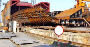

For all practical purposes, a vessel is characterised by a number of segregating divisions or walls throughout its length commonly known as bulkheads.
The science of bulkheads derives from the inherent theory of damage stability, that is, maintaining maximum watertight integrity in the occasion of accidental flooding due to water ingress caused by the breach of the hull or other unwanted situations.
Any good design of a vessel features carefully placed transverse and longitudinal bulkheads based on analysis and pre-estimated scenario of damage stability.
It can be undeniably argued that the disposition and arrangement of such bulkheads in a vessel is a pivotal factor in determining the ‘survival fitness’ of the vessel during accidental situations either from external or internal causes.
By external causes, we mean damage due to collisions or failure of the structure itself due to numerous reasons.
Remember Titanic? The vessel, which was coined as ‘unsinkable’ met its doomed fate over a century ago after colliding with a giant iceberg in the middle of the Atlantic.
Though experts and scientists have asserted that the size of the berg and various other design factors contributed significantly to the dramatic event, the placement of the forward bulkheads also played a significant role.


As water deluged into the forward six compartments, the bulkheads demarcating these areas failed to contain the flow into the remaining ten compartments due to their nature.
First, these transverse bulkheads were not further subdivided by interspersing longitudinal ones to beef up their structural integrity, even considering the fact that the forward or bow region is more susceptible to damage or impact.
Secondly and most importantly, the bulkheads in those regions, even though extending flush horizontally on either side, were not watertight at the top. i.e., they only extended slightly above the maximum waterline.
Hence, as water flowed into the forward compartments, the vessel drastically trimmed and pitched by the bow and the water spilt over to the remaining compartments in succession. Thus, instead of preventing or at least delaying the sinkage of the huge vessel, the error in the design of the bulkheads accelerated the disaster.
So, for a naval architect or an engineer, meticulously designing and placing the bulkheads is a very important part of the overall design spiral.
Furthermore, speaking of internal causes, the holds or compartments in the vessel are rooms for various fluid substances like ballast or freshwater, liquid cargo, or fuels. These need to be carefully demarcated by watertight as well as airtight bulkheads.
Any breach or design or construction errors in such bulkheads will prove to be adverse and once again, jeopardize the stability and integrity of the vessel. Though every bulkhead in a vessel is important, there is one special bulkhead in the fore region of the vessel which is of utmost concern for every designer. This is known as the collision bulkhead.
A collision bulkhead is defined as the foremost watertight transverse bulkhead constructed for almost every vessel to mitigate the inflow of water in case of forwarding damage. This is also reckoned as a ‘second barrier’ of the vessel in the forepeak area.
Let us learn more about this special division.
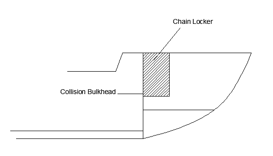
From a point of view of construction, a collision bulkhead extends from the bottommost plating of the vessel (or from the upper floor in case of double-bottom) to the upper deck plating which is either the main freeboard deck or the forecastle deck.
The volume of the hull bound by the collision bulkhead, the bulkhead deck (deck towards which the watertight bulkheads extend), and the hull shell plating of the bow area form what is known as the forepeak region of the vessel.
The forepeak region mostly is characterised by a tank or a compartment known as the forepeak compartment or the forepeak tank. This tank is mostly void or holds ballast water for trim corrections if required.
As per SOLAS guidelines, any form of cargo, fuel, or oily substances is strictly not allowed to be carried in the forepeak tank. However, the chain locker enclosure meant for storage of anchor chain cable (refer article: Parts of Anchor) is mostly housed in the forepeak tank region.
From the structural point of view, the fore region of the vessel is most critical not only because it is susceptible to collisions, but also due to the multitude of stresses generated in the region. The bow of the vessel faces the highest magnitude of the oncoming wave forces.
Other than the dynamic wave loads, the platings in the forward region are also subject to a high degree of structural forces such as panting (a rhythmic structural vibration phenomenon) due to variable water pressure loads as well as effects like bow slamming, racking, and pounding (refer to our previous articles related to these).
So, it goes without saying that all elements of the forepeak are heavily strengthened by various stiffening members as well as characterised by thicker and higher-grade plating. For the same reasons, the collision bulkhead is also given greater consideration.
The thickness of the collision bulkhead is significantly high and is strengthened by horizontal as well as vertical strengthening members to minimize the limit of damage in the event of a head-on collision. The scantlings of the stiffening members are higher than those of the other bulkheads or structures.
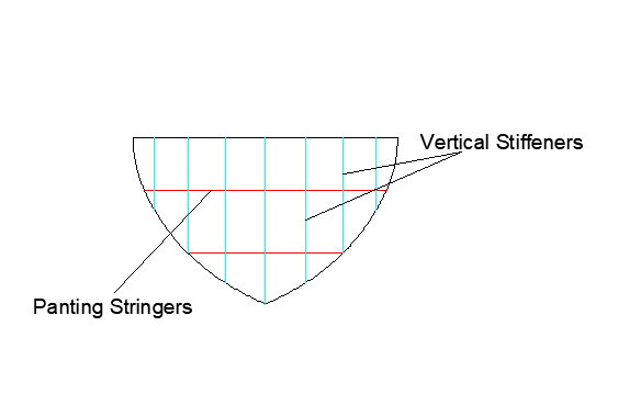
As described above, the forward region is susceptible to high degrees of panting effects. For this reason, horizontal members in the form of stringers of high scantlings are placed successively from the bottom to the top at a regular interval of at most 2 metres also depending on the size of the vessel and the bulkhead.
These are known as panting stringers. For many ships, such stringers are placed in line with the shell stringers for structural continuity. The vertical stiffeners are placed at intervals of 600 mm to 760 mm based on the requirement.
The stiffening members are chiefly of heavy bulb type and are bracketed to the tank-top or the bottom and shell plating. The vertical stiffening members connected to the larger longitudinal strengthening members of the hull have even heavier scantlings for better load distribution.

As already mentioned, they are welded to the bulkhead deck level from the bottom and are strictly watertight. Thus, there are no allowances for permanent accesses, manholes, hatches, ducts, or other openings. However, classification rules allow the provision of up to one pipe for serving the contents of the forepeak tank. As per norms, the incorporation of such an opening is allowed only when:
Though collision bulkheads are mostly planar in nature, they may be stepped or recessed or corrugated if feasible as per classification norms. The watertightness of such a bulkhead is tested using top-notch means such as chalk methods or hose methods.
Because of its high importance, SOLAS and classification societies have definite benchmarks for the placement and arrangement of the collision bulkhead.
As per SOLAS requirements, the position of the collision bulkhead for any oceangoing ship is at least 5% of the length between perpendiculars (LBP) or 10 metres, whichever is less, as measured from the forward perpendicular (Recall definition or refer to any of our previous articles). However, it should not, in any circumstances, exceed a maximum of 8% of the ship’s length or a mathematical sum of 5% of the length and 3 metres (0.05L +3 metres), whichever is greater.
For vessels having forward projections below the waterline, like a bulbous bow, instead of the forward perpendicular, as per regulations, such distances are measured from the least of the following: i) The midpoint of such extension ii) A point at a distance of 1.5% of the length of the vessel ahead from the forward perpendicular iii) A point at a distance of 3 metres from the forward perpendicular.
The final position of the bulkhead within these acceptable limits is decided based on floodable length calculations and the final proposed arrangement with most designs tending to maximize the volume of the forepeak tank.
The forward space of the collision bulkhead should be free of any form of machinery spaces or accommodation.
For vessels having long superstructures extending forward beyond the position of the collision bulkhead, the bulkhead is extended to the next deck level above it and is made fully watertight.

What are your thoughts on the collision bulkhead? Let us know in the comments below.
You might also like to read:
Disclaimer: The authors’ views expressed in this article do not necessarily reflect the views of The Marine Learners. Data and charts, if used, in the article have been sourced from available information and have not been authenticated by any statutory authority. The author and The Marine Learners do not claim it to be accurate nor accept any responsibility for the same. The views constitute only the opinions and do not constitute any guidelines or recommendations on any course of action to be followed by the reader.





We believe that knowledge is power, and we’re committed to empowering our readers with the information and resources they need to succeed in the merchant navy industry.
Whether you’re looking for advice on career planning, news and analysis, or just want to connect with other aspiring merchant navy applicants, The Marine Learners is the place to be.