

The development of GMDSS (Global Maritime Distress And Safety System) for the shipping industry has come a long way. The GMDSS system was established with an objective to improve distress and safety radio communications and procedures at sea.
The greatest benefit of the GMDSS equipment is that it vastly reduces the chances of ships disappearing without a trace, and enables search and rescue (SAR) operations to be launched without delay and directed to the exact site of a maritime disaster.
Gone are the days when ships were required to have dedicated radio officers to operate radio equipment. With the implementation of GMDSS, every deck officer with a General Operator Certificate (GOC) and the license is entitled to use the GMDSS equipment and make radio communications when needed.
For the GMDSS equipment to function properly and effectively in the event of an emergency, it is critical that mariners understand its purpose and do the required maintenance on board the vessel to keep it in a working condition and make the best use of GMDSS equipment.
The daily, weekly and monthly tests of all the GMDSS equipment should be done by every navigating officer responsible for it without any compromise. We must not forget that it is our only best friend in a distress situation at sea.
Ships at sea must be capable of performing the nine functional GMDSS requirements. They are:
This can be ensured by testing the GMDSS equipment at regular intervals.
The GMDSS equipment and systems include the VHF DSC/RT, MF/HF DSC/RT, INMARSAT, SART, EPIRB, NAVTEX, and SURVIVAL CRAFT TWO WAY VHF.
The proper functioning of the Digital Selective Calling (DSC) facilities shall be tested at least once each day, without radiation of signals, by the use of the equipment’s Internal test facility. The daily test checks the internal connection, transmitting output power and the display. The process can differ from equipment to equipment based on the make.
The daily test of the FURUNO model of the VHF equipment can be executed as below:
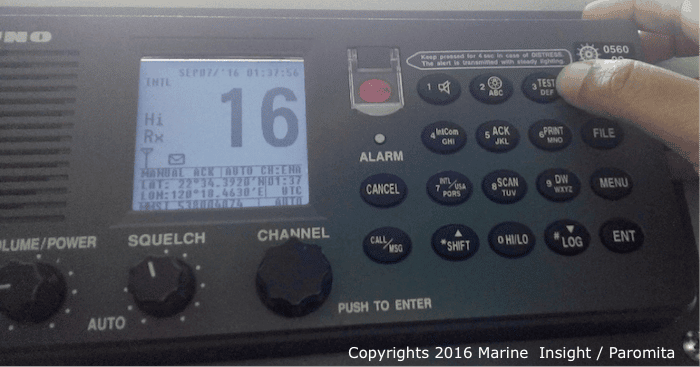
1. At the standby display press, the SHIFT key followed by the TEST key. The “TEST IN PROGRESS” pop up window appears momentarily and distress alarm both visual and audible occurs.

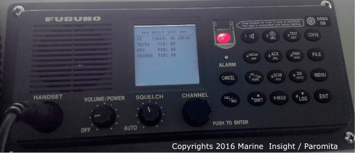
The display shows the TEST screen. If everything is okay with the set and is functioning properly, the results show OK as below. However, in some situation or if it’s a faulty equipment, ‘NG’ may be displayed. In this case the daily test should be repeated a couple of times. If the problem persists, it should be immediately brought to the notice of a shore based service engineer.

2. Press the CANCEL key to stop the alarm. To stop the daily test, press the CANCEL key again.
Daily test also needs to be performed on the MF/HF equipment to ensure it will function properly in the event of distress.
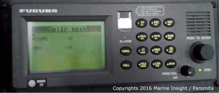
1. Press the [3/TEST] key to start the test. Select the Daily Test by rotating the knob and push to enter. After several seconds the display shows the test results; OK for normal operation. The audio alarm also sounds after the test results are displayed and the alarm lamp flashes several times.



2. The CANCEL key should be pressed to quit the test and return to the normal screen.
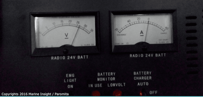
Batteries providing a reserve source of energy should also be checked daily. Mainly the battery ON-LOAD and OFF-LOAD voltages are checked by a voltmeter connected to the charger.
OFF-LOAD: when no equipment is connected, the battery should read 24 V or slightly more.
ON LOAD: switch off the AC power and note the voltage of the battery. Press the PTT on MF/HF transceiver on a non-distress and idle R/T frequency. Voltage will fall depending upon the load. If the voltage falls more than 10% it indicates that the battery is either weak or not charged fully. In this case, batteries should be recharged.


It is also important to check that all printers are in a working condition and there is sufficient supply of paper.
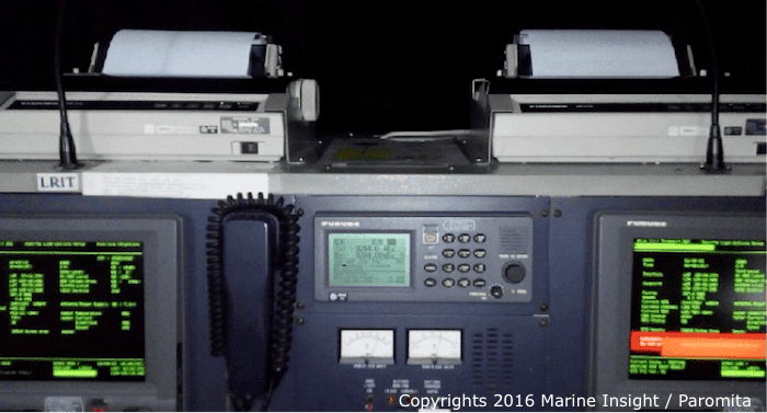

It is necessary to test the proper operation of the DSC facilities at least once a week by means of a test call over one of the six distress and safety frequencies, when within the communication range of a coast station fitted with a DSC equipment. A test call to the coast station can be sent in the following ways:
1. Press the [2/DSC] key at the DSC standby screen and then push the [ENTER] knob to open the CALL TYPE menu.
2. Rotate the [ENTER] knob to choose TEST CALL and then push the [ENTER] knob. Push the [ENTER] knob again to open the COAST ID menu.


3. Using the numeric keys, key in the ID of the coast station ID (seven digits) where you want to send the call depending upon the area you are navigating in and then push the [ENTER] knob. The coast station ID can be found from the Admiralty List of Radio Signals Volume 1- Maritime Radio Stations.
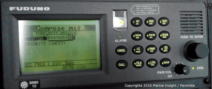

4. Now push the [ENTER] knob to open the DSC FREQ menu. (Note that here the PRIORITY is automatically selected to SAFETY.)
5. Rotate the [ENTER] knob to choose an appropriate frequency and then push the [ENTER] knob.
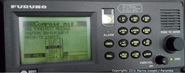

6. Now press the [CALL] key to send the TEST call to the respective shore station.
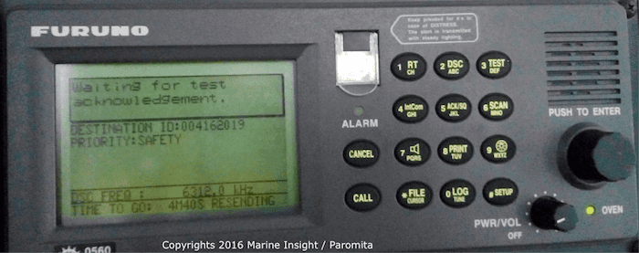

After the test call has been sent successfully the acknowledgement is received from the shore station. The audio alarm sounds on receiving the acknowledgement.
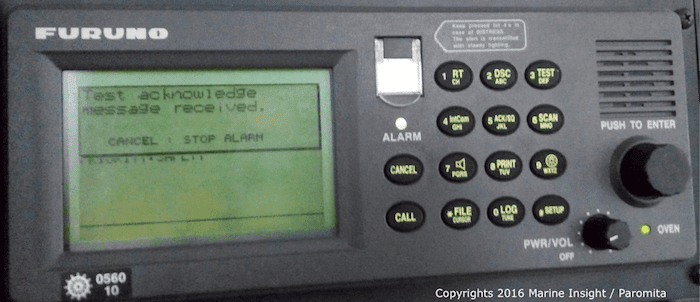

Many times it often happens that the deck officer does not receive any acknowledgement from the shore station. In such cases, we often take it for granted that the shore station is not sending the acknowledgement. However, in reality, this might not be the case.
The problem could be with our equipment too. To make sure that the MF/HF equipment is in order, it is better we try sending the test call using other frequencies and to other stations. Even if then we fail to receive any acknowledgement, a test call can be sent to a passing ship if possible. Instead of keying the coast ID, key in the MMSI of the passing ship. It is better to call the ship and confirm if they have received the test call. We can also request them to send us a test call to ensure that the equipment receiving facility is functioning properly.
It is also recommended that a station to station test takes place using VHF DSC.
1. Press the CALL key. This will open the compose message screen where the call type can be selected. Rotate the channel knob to select TEST call.
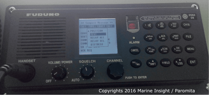

2. Enter the Station ID, in this case, the MMSI of your own ship and then press the CALL key for it to be transmitted.
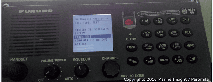

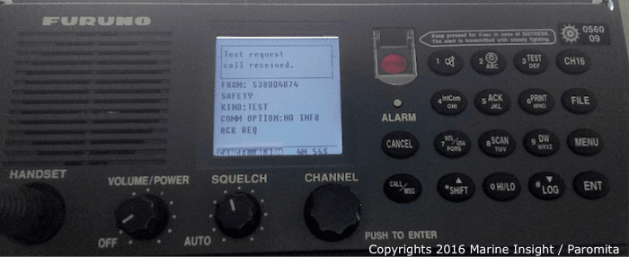

The audio and visual alarm is generated and the test call is received on the other VHF station. Press cancel to terminate the test call.
The Emergency Position Indicating Radio Beacon or EPIRB should be examined by carrying out a self-test function without using the satellite system. No emergency signal is transmitted during the self-test. During self-test the battery voltage, output power and frequency are checked. The EPIRB should also be checked for any physical damage. The expiry date of the battery unit and that of the hydrostatic release unit should be checked. Also, check that the safety clip is properly attached and in place.
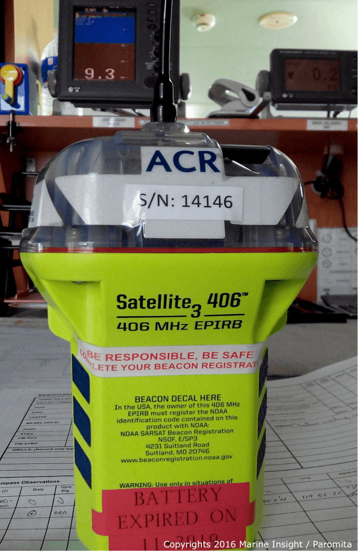

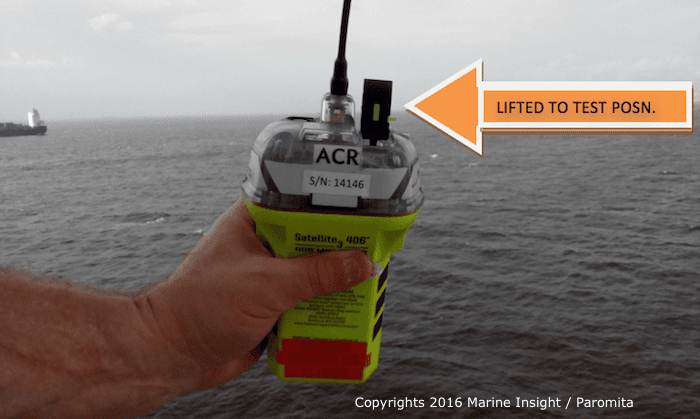
To perform the self-test on the JOTRON EPIRB:
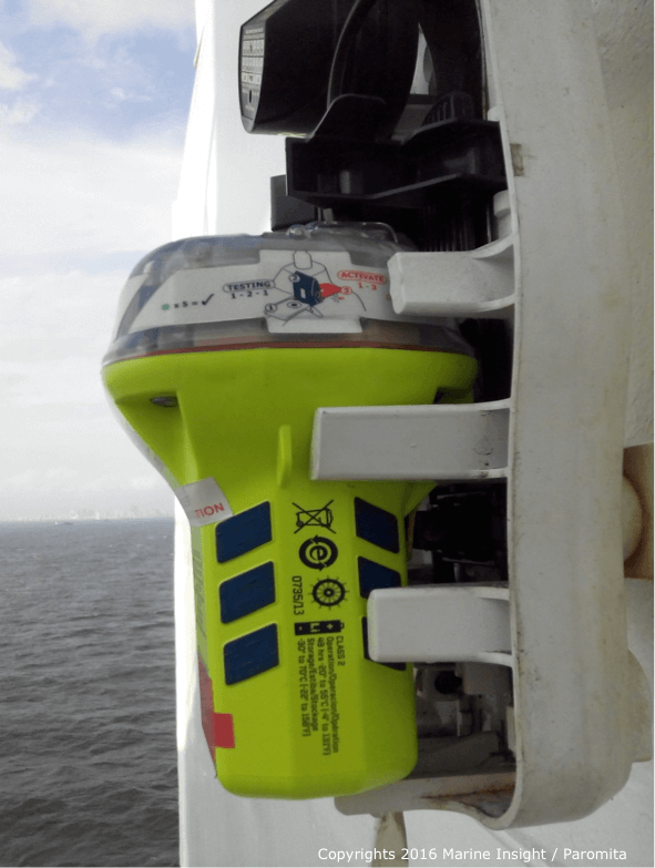

A successful test will consist of a series of blinks on the LED test-indicator, followed by a continuous light and a strobe flash after approximately 15 seconds. The last green led indicates a successful test.

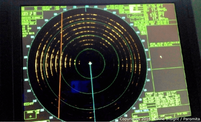
The Search and Rescue Transponder or SART is also equipped with a self-test mechanism to test the operational function of the beacon. The SART is tested using the ship’s X band radar. The test should preferably be done in open seas to avoid interference on the radar display.
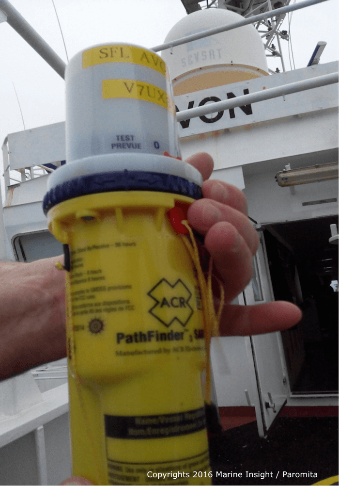

Visual lights operate and bleeps are heard indicating that the SART has been triggered.

Each survival craft two way VHF equipment should be tested at least once a month to ensure proper operation in case of a distress situation. It should be tested on a frequency other than VHF channel 16 (156.8 MHz). The expiry date of the battery needs to be checked and changed when required.
1. Press the power key to switch on or off.
2. To select a different channel, press the CH key and use the arrow keys to select the required channel. The selected channel is indicated with channel number and frequency on the screen.
3. Press the PTT (Push to talk) to communicate with another radio-telephone to test receive and transmit functions. One person can stand near the VHF receiver to receive a test call from the handheld radio.
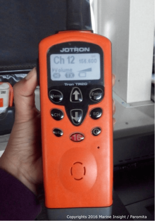

The symbol ‘TX’ is shown when the PTT is pressed and transmission takes place. The TX indicator indicates that a carrier is produced at the antenna output.
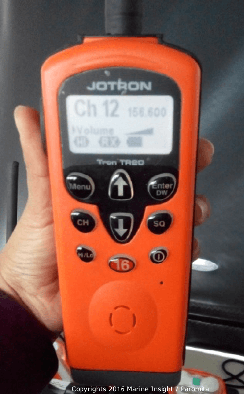
When it receives a signal the symbol ‘RX’ is indicated on the display.

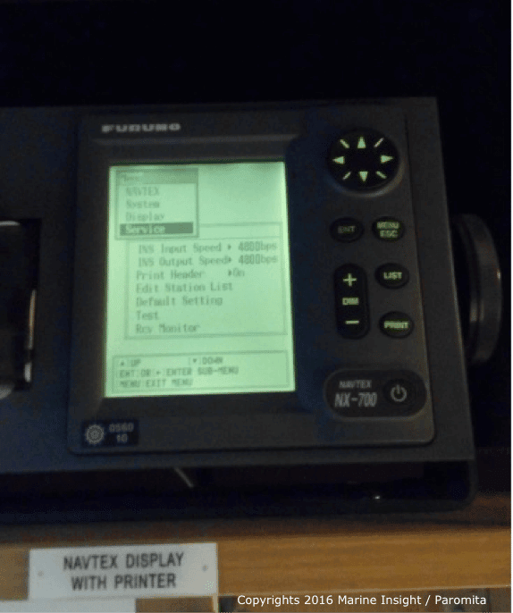
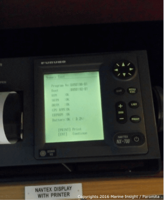
The Navtex is an equally important GMDSS equipment and is the source of maritime safety information. It is also equipped with a test function that can test the battery, keyboard, LCD, ROM and RAM. It is a good practice to test the Navtex and detect an error if any. The Furuno model of Navtex can be tested as follows:
1. Press the MENU/ESC key to open the main menu.
2. Now use the navigating arrows to choose SERVICE and then hit ENT. The SERVICE submenu contains the TEST option. Use the down arrow key to select TEST and press ENT key. Choose YES and press the ENT key again. The TEST will start and the results will be displayed on the screen after a few seconds.

If the test is successful the results show OK otherwise it will show NG meaning – No Good.

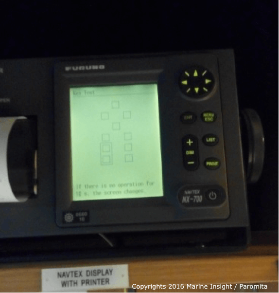
It also tests each key for proper functioning.

The Rx test screen shows as follows:
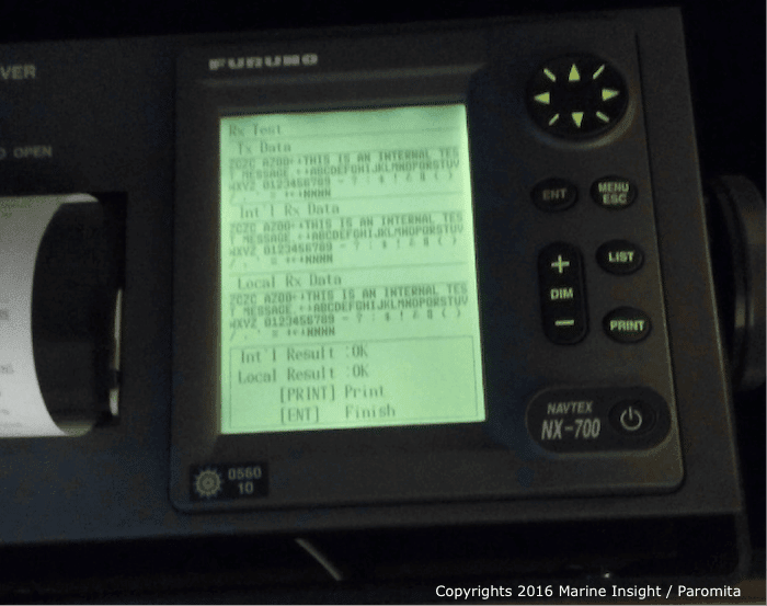

The test results can be printed and filed in the GMDSS log book.
The INMARSAT is also equipped with a diagnostic test which checks it for proper operation. The steps to perform a Diagnostic Test on FURUNO INMARSAT are given below;
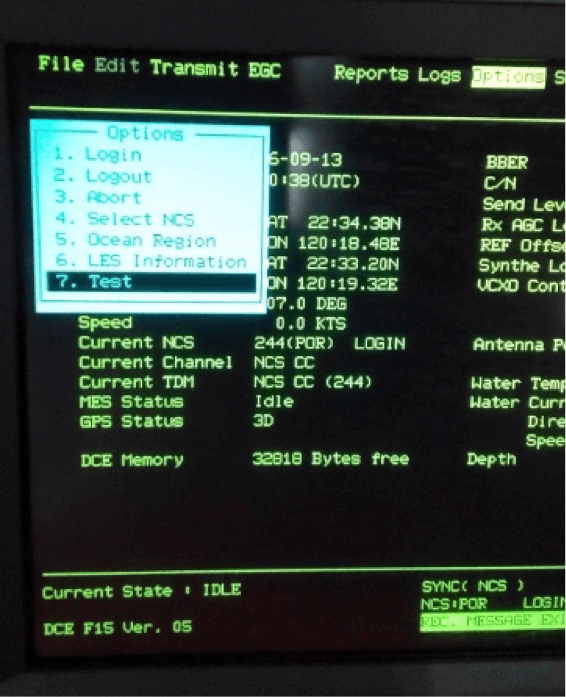

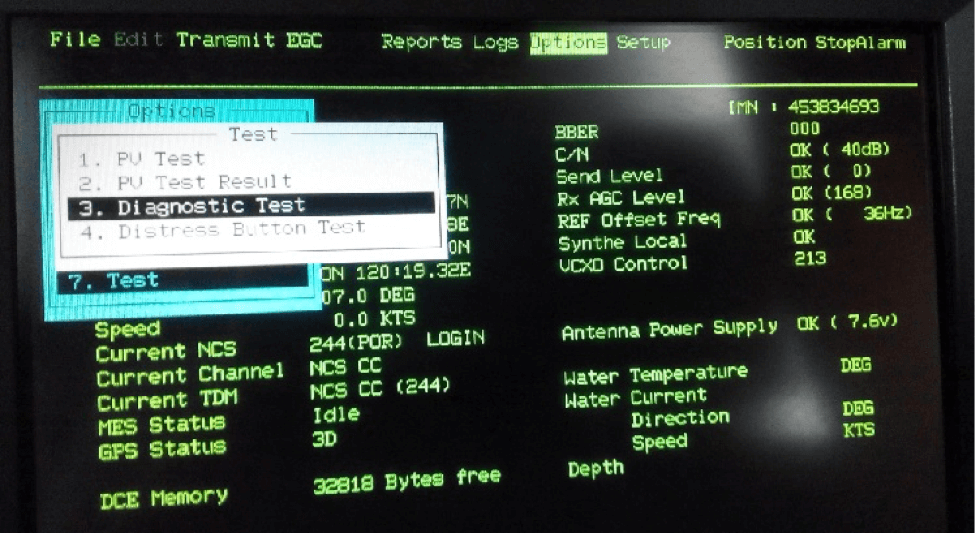


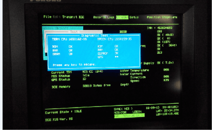
On completion of the test, the results are shown on the screen as below. The ESC key is used to return to the main menu.

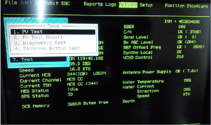
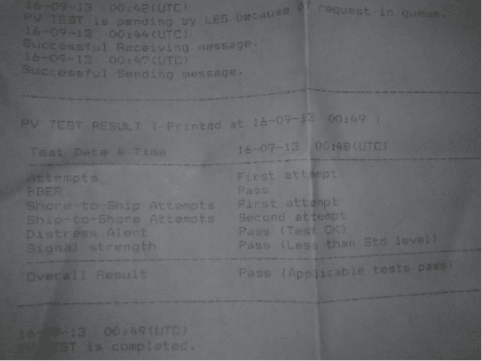
A PV test or Performance Verification test can be performed every month. This test consists of receiving a test message from an LES (Local Earth Station), transmitting a message to an LES and a distress alert test. The PV TEST can be opened from the TEST menu under OPTIONS as mentioned above.

The status shows ‘TESTING’ when the test is in process.


The status changes to IDLE on completion of the PV Test.
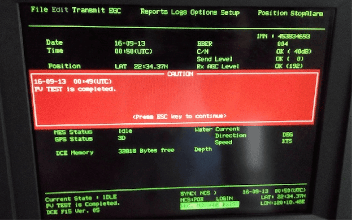

The test results can be seen from the option ‘PV Test Result’ under the TEST menu. The test results can be printed and logged. BBER denotes the bulletin board error rate. Pass appears for no error. “PASS” appears for satisfactory completion of the test.

The battery connections and compartment should also be checked. The level of the electrolyte and the specific gravity of each cell should be checked and recorded. Sulfation can reduce the specific gravity thereby reducing the battery capacity. Maintenance free batteries on board, however, do not require any such checks.
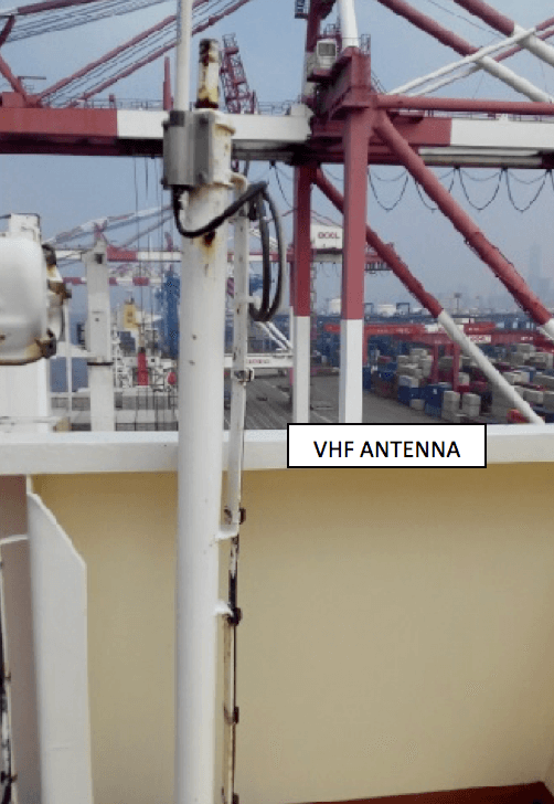

It is recommended every month to visually check all antennas for the security of mounting and visible damage to the cables. The antennas are located on the monkey island. Any deposit of dirt and salt should be removed. It is also important to check the condition of the aerials and insulators along with the help of an electrical officer. Ensure that the equipment is switched off and isolated before carrying out any work on the antenna.
GMDSS enables a ship in distress to send an alert using various radio systems. It is therefore important that all the GMDSS equipment are maintained in a state of readiness and working condition. To achieve this it is mandatory to perform the daily, weekly and monthly tests. Only then can we ensure the safety of the ship and its crew.
Disclaimer: The authors’ views expressed in this article do not necessarily reflect the views of The Marine Learners. Data and charts, if used, in the article have been sourced from available information and have not been authenticated by any statutory authority. The author and The Marine Learners do not claim it to be accurate nor accept any responsibility for the same. The views constitute only the opinions and do not constitute any guidelines or recommendation on any course of action to be followed by the reader.
The article or images cannot be reproduced, copied, shared or used in any form without the permission of the author and The Marine Learners.


We believe that knowledge is power, and we’re committed to empowering our readers with the information and resources they need to succeed in the merchant navy industry.
Whether you’re looking for advice on career planning, news and analysis, or just want to connect with other aspiring merchant navy applicants, The Marine Learners is the place to be.