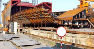

The hull is the main floating body of any vessel and contributes to the buoyancy that keeps the vessel afloat by displacing water, as defined in Archimedes’ principle.
From a structural point of view, the hull is watertight or intact from its outer shell and is closed at the top by the main deck or the weather deck.
This deck is also known as the strength or the exposed deck for all practical purposes. Any structural entity above this main deck level is known as the superstructure or deckhouse.
Now, coming to the main hull, the different parts of it can be defined from different perspectives.
As we know, the main longitudinal and transverse strength of any vessel can be defined from the hull girder strength.
Technically, this means that all form of loading is directly acted upon the hull. Thus, the structural design of this is the main determinant in assessing the load-absorption capacity of the ship structure.
The superstructure or deckhouse contributes to the structural strength of a vessel but mainly in a local way.
In other words, all local effects on the structure arising from direct load or vibrational effects are best manifested on the superstructure or deckhouse.
However, from a global load point of view, most of the effects are based on the response of the hull structure itself.


For instance, the principal two components of the longitudinal responses of the vessel due to global loading, namely, sagging or hogging, are described in terms of the behaviour of the hull structure as a simply supported beam.
In other words, the effects of longitudinal loading on a vessel can be defined by considering it as a beam where the hydrodynamic and hydrostatic loads are acting as forces and the hull structure, as a whole, behaves like a bending beam.
Similarly, for transverse cases of loading that act on the vessel in a direction perpendicular to its centreline, the hull structure behaves accordingly depending on the magnitude and the nature of loads oncoming.
Thus, to sustain these transverse and longitudinal loads acting on the hull structure as a whole, there is an array of strengthening members in conjunction with the various kinds of external and internal plating, as we know.
As we know, longer vessels with a greater length-to-breadth ratio have more pronounced effects of longitudinal loads as compared to transverse. Similarly, shorter vessels with a lower length-to-breadth ratio have more significant effects of transverse loading as compared to longitudinal.
Furthermore, from a purely structural point of view, the various entities of a hull can be classified as:
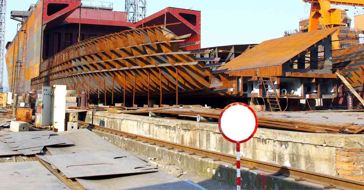
This is the outer structure of the main hull that is composed of welded plates of various scanting and sizes. For a majority of vessels, the material for the outer shell plating is steel of different high breeds, while for some vessels, composites like FRP or aluminium are used.
Before the advent of steel on a wide scale, iron was used extensively, preceded by wood in the previous ages of history.
The outer hull plating can be further subdivided as:
These are the plates which lie in the lower region of the hull. Now, the exact definition of the bottom shell plating depends on the design of the vessel but is usually used for the flat or inclined plates that start from the baseline of the vessel and continue on either side.
The plate that is concurrent with the centreline of the vessel is known as the keel.
This is the plate that has the heaviest amount of scantling in the entire vessel for all practical purposes; that is, this plate has the most thickness.


The reasons are many: the bottom of the ship is the area which suffers the highest magnitude of structural loads and also absorbs all the connecting loads coming from the rest of the vessel. And all the loads are also maximum near the centreline of the vessel. Moreover, during instances of deflections and buckling, this particular region also suffers the maximum extent of displacement or deformation tendency under different effects of loading.
For many ships, the upper side of the bottom shell structure has a curvature, and this curved plate is also known as the bilge plate or turn of the bilge. The plates that are right adjacent to the keel on either side are known as garboard strake and also have a significant amount of thickness.
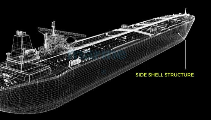

The array of plates from bottom to top just adjacent to the bottom structure is known as the side shell plating. These plates are of vertical orientation and define the side extents of any vessel.
The uppermost plates of the side shell that is right adjoining to the upper deck are known as the shear strake. These plates are also of higher scantling as they are subject to high degrees of shear loading.
The deck is nothing but a horizontal and continuous surface of significant dimensions in the ship structure. The word significant is important. This is because, for all practical purposes, a deck needs to extend at least a few frames in length and should have some minimum breadth as well, preferably from side to side.
Smaller decks may also exist based on requirements. Sometimes these intermittent, small, randomly placed decks are known as platform decks, which do not contribute significantly to the overall strength of the vessel.
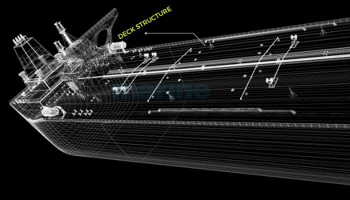

Now, as we know, the main deck comprises the uppermost limit of the main hull. For all practical purposes, it is often fully or partially exposed to external weather conditions and is known as the weather or exposed deck.
Moreover, as it significantly contributes to the longitudinal strength of the hull girder, it is known as the strength deck. There may be other decks inside the main hull or superstructure as well, and for larger vessels, there is a definite numbering system for the decks successively based on the height from the bottom line.
Some common deck names in the superstructure or deckhouse are Bridge deck, bridgedeck top, wheelhouse top, and so on.
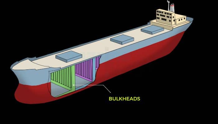

Bulkheads, as we know, are demarcations or separations that separate two compartments or spaces. They are either longitudinal or transverse in nature.
As these are connected between two decks or levels, they are important members that contribute to the strength of the vessel.
They are situated in both the main hull and the superstructure. Boundaries are similar to bulkheads and are often used for tanks or compartments of different sizes.
Now, as we all are aware, the vessel needs to be structurally strengthened at every location to sustain all types of loads from both local and global perspectives. The strengthening members can be categorised as follows:
These members are the main members that contribute to the strength. Though separately categorised, the structural plates (shells), decks, and bulkheads (if they are beyond a certain length or span) are primary members themselves.
Other than that, the different kinds of primary members are basically the deep members, like deck beams, bottom shell girders, side frames, vertical beams, and so on. They are directly responsible for absorbing most of the global loads that are oncoming to the vessel structure.
These basically include the stiffening members. They are the transverse, longitudinal or vertical stiffeners or other beams like pillars or stanchions. They essentially take the loads transferred from the primary members and, at the same time, also support the primary members.
For example, the longitudinal stiffeners are responsible for absorbing the loads coming from the deck plates and the girders and succouring to the longitudinal strength. Similarly, the vertical stiffeners supporting the bulkhead are responsible for absorbing the loads from the bulkhead frame and the plates.
These secondary members have lower scantlings than deep members and are more frequent in number at a certain spacing. They may be continuous in nature or interspersed by other members.
They include entities like brackets, flat plates, bars, insert plates, and so on. These are strengthening members which are associated with the secondary members, often providing them with support and connectivity.
For instance, the brackets can provide support, and also connectivity between a longitudinal stiffener on a deck and a vertical stiffener at a bulkhead may define a load path for the transfer of forces.
Often, they are also used for localised strengthening along with secondary members at certain locations. For instance, in the way of a deck opening, additional flat bars along with small stiffeners may be used for localised strengthening in order to compensate for the loss in strength near that area.
Other members include A-brackets, couplings in the way of machine spaces or engine rooms, corrugated stairs, perforated plates, checker plates, and so on.
We are more or less familiar with classification. The region near the back of a vessel is now the aft or the aft region. Similarly, the region close to the front quarters is known as the bow region or bow quarters.
The extreme limit of the aft is also stern. These two regions have a high incidence of global loads. The maximum part abutted by these two entities is known as the parallel middle body.
This region is more or less continuous with lesser curvature. We have defined the decks above. The part of the outer hull above the waterline is often the topside.
You might also like to read-
Disclaimer: The authors’ views expressed in this article do not necessarily reflect the views of The Marine Learners. Data and charts, if used, in the article have been sourced from available information and have not been authenticated by any statutory authority. The author and The Marine Learners do not claim it to be accurate nor accept any responsibility for the same. The views constitute only the opinions and do not constitute any guidelines or recommendations on any course of action to be followed by the reader.
The article or images cannot be reproduced, copied, shared, or used in any form without the permission of the author and The Marine Learners.







We believe that knowledge is power, and we’re committed to empowering our readers with the information and resources they need to succeed in the merchant navy industry.
Whether you’re looking for advice on career planning, news and analysis, or just want to connect with other aspiring merchant navy applicants, The Marine Learners is the place to be.