
Synchronization of Generators is the process of matching parameters such as voltage, frequency, phase angle, phase sequence, and waveform of an alternator (generator) or other sources with a healthy or working power system. A generator cannot supply electricity to an electric power system unless its voltage, frequency, and other parameters are precisely matched to the network. The exciter current and the generator’s engine speed are controlled to achieve synchronization.
Synchronization is primarily needed when two or more alternators work together to supply power to the load. Electrical loads are very inconsistent and they vary with time (depending on the load) and so it is necessary to interconnect the alternators operating in parallel to supply larger loads.
It ensures that the various parameters of one alternator ( or generator) resonate with another alternator or with the bus bar. The process of synchronization is also known as Paralleling of Alternators or Generators.
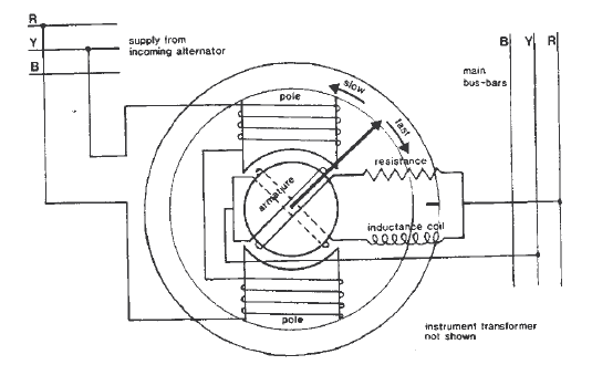
The synchronizing of the generator is done with the help of a synchroscope or with the three-bulb method in case of an emergency. It is of utmost importance that before paralleling the generators, the frequency and voltage of the generators need to be matched. In this article, we will describe the method for synchronizing generators on a ship.
The synchronous generator comprises a rotor and a stator similar to a standard generator. The rotor consists of an electromagnet that rotates in the stator. The stator comprises windings that induce a 3- phase voltage and it consists of three stationary coils known as a stator, armature, or phase coils. Magnetization is also crucial for the stator windings because in absence of magnetic fields there are no forces to create currents.
To calculate the synchronous speed of the generator we use the formula-
Ns=(120 * f) / P
Where:
Ns = Synchronous speed, rpm
f = Frequency, Hz
P = Number of poles
120 is a constant for the time (seconds/minutes) and pole pairs, to get the speed in rpm.
There are certain conditions that have to be met for the successful paralleling of generators. The underlying conditions must be met in order to synchronize a generator to the grid or with other generators.
The phase sequence of the three stages of the alternator connected to the power system bus must be identical to the phase sequence of the three phases of the bus bar (or electric grid). This issue usually arises during the initial installation or during routine maintenance.
The incoming alternator’s RMS voltage should be the same as the bus bar or electric grid’s RMS voltage. There will be a lot of reactive power flowing from the generator into the grid if the incoming alternator voltage is higher than the bus bar voltage.
The generator absorbs the high reactive power from the bus bar if the input alternator voltage is lower than the bus bar voltage.
The frequency of the incoming generator must match the bus bar’s frequency. Inadequate frequency matching causes the prime mover to accelerate and decelerate rapidly, increasing the transient torque.
There should be no phase angle between the incoming generator voltage and the voltage of the bus bar. By comparing the occurrence of zero-crossing or peaks in the voltage waveforms, this can be seen.
There are two methods to synchronize generators on a ship – one is the normal and the other is the emergency method.


A synchroscope is used to check the consequent frequency difference between the generators and the grids’ voltages.


This method is generally used when there is a failure of the synchroscope. In case of failure, a standby method should be available to synchronize the alternator, and thus the emergency lamp method is used.
Three lamps should be connected between three phases of the bus bar and the incoming generator should be connected.
The ON and OFF rate of these lamps is determined by the frequency difference between alternator-2 voltage and bus bar voltage. As a result, the flickering rate must be lowered to match the frequency. This is accomplished by regulating the alternator’s speed via the prime mover control.
The bulbs will turn dark once all of these parameters have been established, and the synchronizing switch can then be closed to synchronize alternator-2 with alternator-1.
The biggest disadvantage of this method is that it only shows the difference between the alternator-2 and the bus bar by measuring the rate of flickering. However, this method does not provide information on alternator frequency in relation to bus bar frequency.
This method can be used to determine whether the alternator frequency is lower or higher than the bus bar frequency.
The downside of this method is that the phase sequence’s validity cannot be verified. This criterion, on the other hand, is superfluous for permanently connected alternators, where confirming the phase sequence is sufficient for the first time of operation.
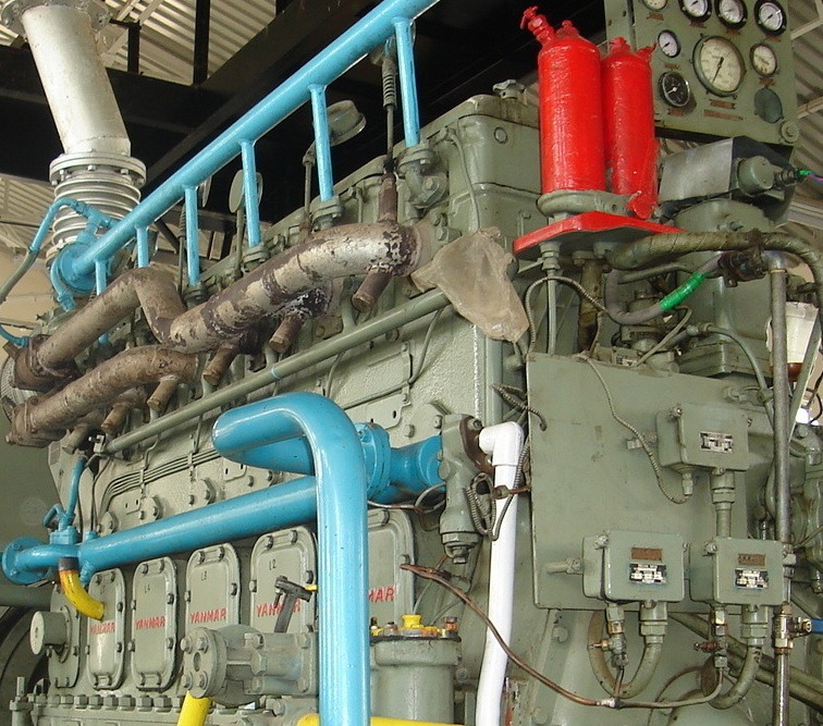
References and Image Credits: marine electrical equipment and practice by H.D Mcgeorge, generator arrangement – www.boatnerd.com


We believe that knowledge is power, and we’re committed to empowering our readers with the information and resources they need to succeed in the merchant navy industry.
Whether you’re looking for advice on career planning, news and analysis, or just want to connect with other aspiring merchant navy applicants, The Marine Learners is the place to be.