
Several electrical machines and panels are fitted onboard ships to sail from one port to another safely and efficiently.
The electrical machinery and system require scheduled maintenance and checks to avoid any breakdown during sailing.
Different instruments are used onboard for measuring several electrical parameters to analyze and keep these machines in proper running condition.
A permanent magnet moving coil (PMMC) is one such instrument that is popularly used onboard and has several applications. The other popular nomenclature of this instrument is D’alvanometer and galvanometer.
When a current-carrying conductor is placed in a magnetic field, it experiences a force and tends to move in the direction as per Fleming’s left-hand rule.
Fleming left-hand rule:
If the first and the second finger and the thumb of the left hand are held so that they are at a right angle to each other, then the thumb shows the direction of the force on the conductor, the first finger points towards the direction of the magnetic field and the second finger shows the direction of the current in the wire.
The interaction between the induced field and the field produced by the permanent magnet causes a deflecting torque, which results in the rotation.
The three important torque involved in this instrument are:
Deflecting torque:
The force F, which will be perpendicular to both the direction of the current flow and the direction of the magnetic field as per Fleming’s left-hand rule, can be written as
F = NBIL
where N: turns of wire on the coil
B: flux density in the air gap
I: current in the movable coil
L: vertical length of the coil
Theoretically, the torque (here electro-magnetical torque) is equal to the multiplication of force with distance to the suspension point.
Hence Torque on the left side of the cylinder TL = NBIL x W/2 and torque on the right side of the cylinder TR = NBIL x W/2
Therefore the total torque will be = TL + TR
T = NBILW or NBIA where A is an effective area (A= LxW)
Download Practical Maritime eBooks With Amazing Bonuses:
Here are a few fantastic ebooks to get important maritime information in the next couple of minutes!
This torque is produced by the spring action and opposes the deflection torque so as the pointer can come to rest at the point where these two torques are equal (Electromagnetic torque = control spring torque). The value of control torque depends on the mechanical design of spiral springs and strip suspensions.
The controlling torque is directly proportional to the angle of deflection of the coil.
Control torque Ct =Cθ where, θ = deflection angle in radians and C = spring constant Nm /rad .
This torque ensures the pointer reaches an equilibrium position, i.e. at rest in the scale, without oscillating to give an accurate reading. In PMMC, as the coil moves in the magnetic field, eddy current sets up in a metal former or core on which the coil is wound or in the circuit of the coil itself, which opposes the motion of the coil resulting in the slow swing of a pointer and then come to rest quickly with very little oscillation.
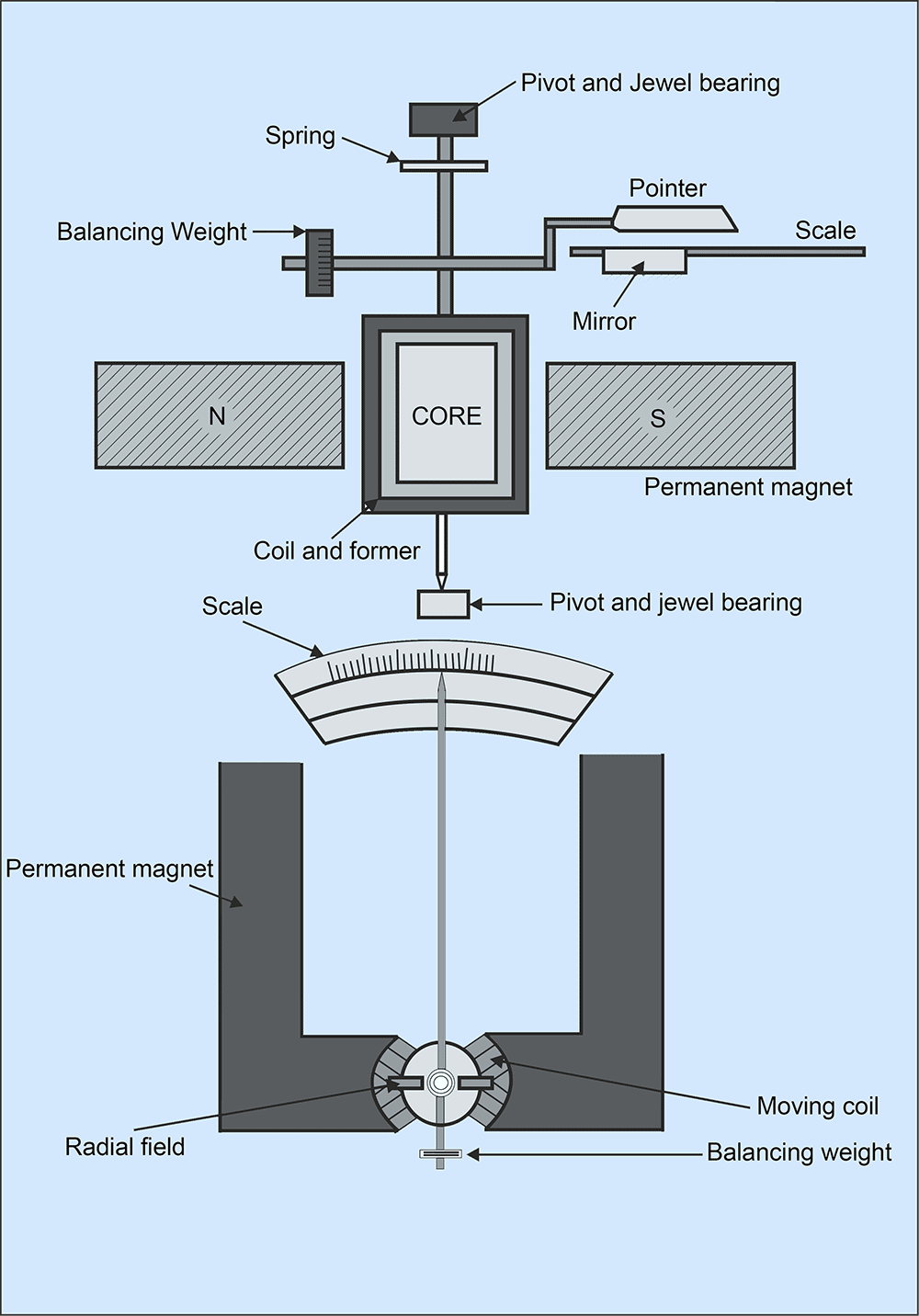
A coil of thin wire is mounted on an aluminium frame (spindle) positioned between the poles of a U shaped permanent magnet, made up of magnetic alloys like alnico.
The coil is pivoted on the jewelled bearing, and thus the coil is free to rotate. The current is fed to the coil through spiral springs, which are two in numbers. The coil which carries a current, which is to be measured, moves in a strong magnetic field produced by a permanent magnet and a pointer is attached to the spindle, which shows the measured value.
When a current flow through the coil, it generates a magnetic field proportional to the current in an ammeter. The deflecting torque is produced by the electromagnetic action of the current in the coil and the magnetic field.
When the torques are balanced, the moving coil will stop, and its angular deflection represents the amount of electrical current to be measured against a fixed reference, called a scale. If the permanent magnet field is uniform and the spring linear, the pointer deflection is also linear.
The controlling torque is provided by two phosphorous bronze flat coiled helical springs. These springs serve as a flexible connection to the coil conductors.
Damping is caused by the eddy current set up in the aluminium coil, which prevents the oscillation of the coil.
The PMMC has a variety of uses onboard ships. For example, it can be used as:
1) Ammeter:
When PMMC is used as an ammeter, except for a minimum current range, the moving coil is connected across a suitable low resistance shunt so that only a small part of the main current flows through the coil.
The shunt consists of several thin plates made up of alloy metal, which is usually magnetic and has a low-temperature coefficient of resistance, fixed between two massive blocks of copper. A resistor of the same alloy is also placed in series with the coil to reduce errors due to temperature variation.
2) Voltmeter:
When PMMC is used as a voltmeter, the coil is connected in series with high resistance. The rest of the function is the same as above. The same moving coil can be used as an ammeter or voltmeter to interchange the above arrangement.
3) Galvanometer:
The galvanometer is used to measure a small value of current along with its direction and strength. It is mainly used on board to detect and compare different circuits in a system.
5) Ohm Meter:
The ohmmeter is used to measure the resistance of the electric circuit by applying a voltage to resistance with the help of a battery. A galvanometer is used to determine the flow of current through the resistance. The galvanometer scale is marked in ohms, and as the resistance varies since the voltage is fixed, the current through the meter will also vary.
If the frequency is low enough, the PMMC with a rectifier can measure AC which converts the measured quantity into a DC typically less than 1mA. Add an appropriate scale, and you have a meter.
If the frequency of ac is high, the meter vibrates in and around the zero value (preferable to verify with a centre zero meter) and finally stops responding to ac
Permanent magnets are made of special alloys such as :
You might also like to read:
Disclaimer: The authors’ views expressed in this article do not necessarily reflect the views of The Marine Learners. Data and charts, if used, in the article have been sourced from available information and have not been authenticated by any statutory authority. The author and The Marine Learners do not claim it to be accurate nor accept any responsibility for the same. The views constitute only the opinions and do not constitute any guidelines or recommendation on any course of action to be followed by the reader.
The article or images cannot be reproduced, copied, shared or used in any form without the permission of the author and The Marine Learners.