The concept of hydrostatics and stability can be deemed as one of the most important areas of focus in ship design and operation, not only to ensure the safety of the ship, cargo, crew and passengers but also to enable proper conditions for completion of all the processes on a ship.
This series of articles will first discuss the concept of hydrostatics of a ship and slowly transition into an introduction of ship stability. Once that is done, we will see how the concepts are applied in real-time and probable situations to analyse the stability of the ship, how a designer applies concepts of hydrostatics and stability to develop a hull form, and so on.
Ship Hydrostatics:
Some characteristic parameters calculated for a floating ship, which can either directly be used to comment on the nature of stability of the ship or be used to evaluate other stability parameters, are called ship hydrostatics. For a designer to be able to develop a hull form, or a ship’s captain to understand the stability parameters, it is important for both to be able to understand the meaning and practical significance of each hydrostatic parameter of a surface ship. We will first list the hydrostatics of a surface ship, and then move on to define them.
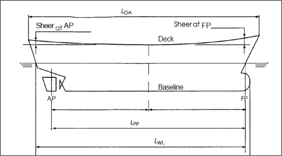
To understand hydrostatics, we need to acquaint ourselves with a few basic ship terminologies that often appear in the process of understanding and evaluating of hydrostatics and stability parameters of a surface ship. Follow the figure below with reference to the terminologies described underneath.
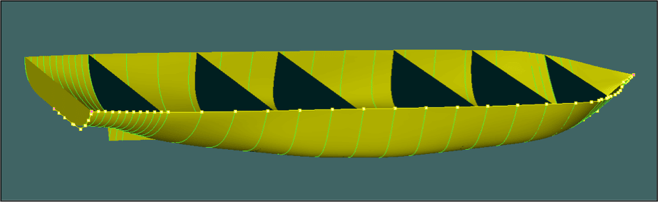
Before we move on, another important technique used in the calculation of ship hydrostatics and stability parameters is that of stations. A ship’s hull is longitudinally divided into stations, which are nothing but specified positions along the length of the ship with reference to the aft perpendicular which is numbered as zero station.
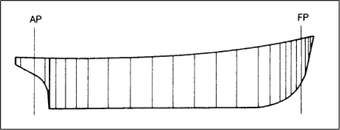
The distance between each station remains constant in the vicinity of the midship where a significant parallel mid-body shape prevails. But as we move towards the aft or forward, the shape of the hull attains a complex geometry, and hence for better results of analyses, the distance between the stations are reduced.
1. Center of Gravity (CG):
The longitudinal position of the CG with respect to any reference point on the ship is called the longitudinal centre of gravity (LCG). Usually, the reference point for locating the LCG is either of the forward or aft perpendiculars.
The vertical distance (along the ship’s centerline) between the keel and the centre of gravity is expressed as ‘KG’, as shown in Figure 2.
2. Center of Buoyancy (CB):
The longitudinal position of the centre of buoyancy with respect to any reference point on the ship is called the longitudinal centre of gravity (LCB). Usually, the reference point for locating the LCG is either of the forward or aft perpendiculars.
The vertical distance (along the ship’s centerline) between the keel and the centre of buoyancy is expressed as ‘KB’, as shown in Figure 3.
3. Metacenter (M):
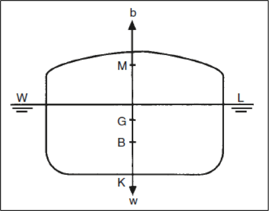
Refer to the following figure to understand that when a ship heels to any angle, a portion of the lower side of the ship is now submerged, and a portion of the hull from the upper side emerges out of the water. This can be noticed by visualizing the hull when the waterline was WL (without heel), and when the waterline was changed to W1L1 (after heel).
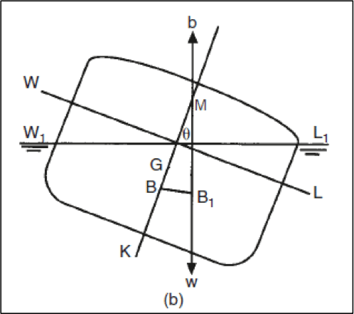
Due to this shift of submerged volume, there is a shift of the center of buoyancy from the centerline to the side that is lower after the heel. The new position of center of buoyancy is illustrated as B1. If a vertical line is extended from the new center of buoyancy, then the point at which this line meets the centerline of the ship, is called the transverse metacenter (shown as ‘M’) of the ship.
4. Center of Floatation (LCF):
When the ship floats at a particular draft, any trimming moment acting on the ship would act about a particular point on the water plane. This point is the centroid of the area of the water plane, and is called the center of the floatation. The distance of the center of floatation is read with respect to either of the perpendiculars or the mid-ship, and is abbreviated as LCF.
5. Metacentric Radius (BM):
The metacentric radius of a ship is the vertical distance between its center of buoyancy and metacenter (refer to figure 3 or 4). This parameter can be visualized as the length of the string of a swinging pendulum of the center of gravity of the pendulum coincides the center of buoyancy of the ship. In other words, the ship behaves as a pendulum swinging about its metacenter. It is a different fact that, the metacenter of the ship changes itself, every moment. Why? Because with every angle of heel, the transverse shift in center of buoyancy (as shown in Figure 4) will vary, therefore creating a new metacenter.
The importance of this parameter can be realised when the mathematical expression of metacentric radius is investigated.
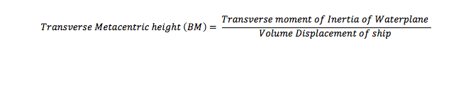
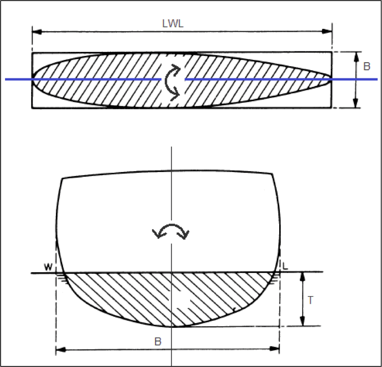
Now, what is the transverse moment of inertia of water plane? Refer to the figure below. A ship floating at a particular draft (T), has a unique water plane. When the ship rolls in the condition, if one looks from the top, the entire water plane area seems to oscillate about its longitudinal centroidal axis (shown in blue). The area moment of inertia of this waterplane area about its centroidal axis is the transverse moment of inertia of waterplane at the corresponding draft.
In the later part of this series, we will see the vital role this parameter plays in the stability of a surface ship, and how it also determines a lot of design decisions.
6. Metacentric Height (GM):
The vertical distance from the center of gravity to the metacenter is called the metacentric height. You will come across this term numerous times in this article, and a designer is probably most concerned about this parameter during the entire design process. IMO Codes of Stability for Ships have laid stability criteria for ships that are mostly based on this parameter. So, what is it that makes this parameter so vital? That is something we will discuss for the most part of the later part of this article, and the next few parts of this series.
The value of GM needs to be obtained at various stages, right from initial design stage, to hull design stage, during stability analysis of a newly designed hull, after the construction of a ship, and during operations at sea. The methods used in these stages are different from each other, because:
For now, given the fact that we know the parameters: BM, KB, and KG, let’s just appreciate the most basic formula used to evaluate the metacentric height of a ship: (refer to figure 3 for visual assistance)
![]()
7. Moment to Change Trim by 1 Centimeter (MCT):
For a particular draft, it is the longitudinal moment (about the LCF) required to bring about a trim of 1 centimeter. This parameter plays vital role especially when the crew on board requires to load cargo in any one hold or ballast, or de-ballast, and predict the resultant trim caused by the action. Since the expression of this parameter does not play any significant role in understanding the concepts of ship stability, we will skip it. But do remember that, MCT is a very important hydrostatic parameter required by stability analysis softwares and crew operations.
8. Tonnes per Centimeter Immersion (TPC):
For a particular draft the weight required to be added onto the ship so as to cause a parallel sinkage of 1 centimeter, is expressed as the TPC. This, similar to MCT, is used extensively by the crew to predict the new drafts after any operation that involves addition or removal of weights from the ship. Following is the expression used to evaluate the TPC of a ship at any given draft:
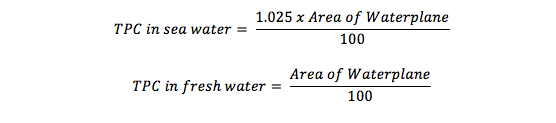
The above expressions give us some important results:
Hydrostatic Curves:
All the hydrostatic parameters are calculated by a stability analysis software and plotted on a graph against different drafts. This graph is collectively called hydrostatic curves, and the same for a 200 passenger ship is shown below.
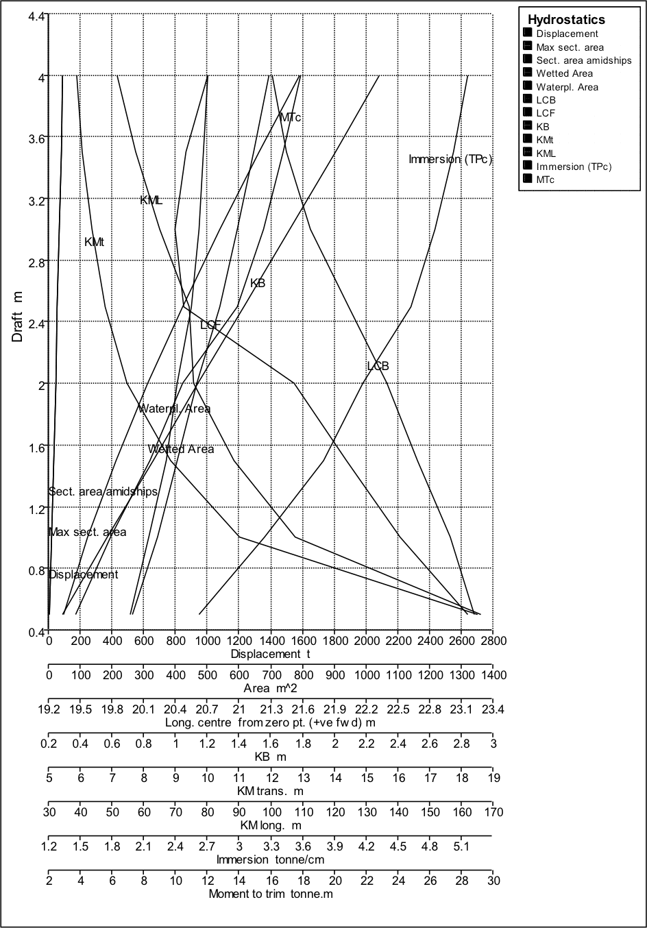
This graph is used by the crew on-board to instantly obtain the value of a hydrostatic parameter of the ship for a given draft. However, one needs to be careful about the multi-scale horizontal axis that is used here, since multiple parameters with different units are plotted on the same graph.
Some important observations can be made by studying the nature of hydrostatic curves, and they are discussed below:
A fine stern means, with increase in draft, the percentage of submerged volume towards the forward of the midship increases more rapidly than the submerged volume in the aft. Hence, at larger drafts, a majority of the submerged volume will be concentrated towards the forward of the midship.
If this would have been a ship with finer bow and fuller stern, an increase in draft would have caused the LCB to shift towards the aft, thereby showing opposite nature on the hydrostatic curve. A ship designer can therefore predict the hullform of a ship just by looking at its LCB curve.
The MCT of all surface ships usually increase with increase in draft. Which means, a surface ship is very sensitive to trimming moments while floating in low draft conditions.
8. Curves of Form:
The various parameters of form (Block coefficient- CB, Prismatic Coefficient- CP, Water plane area coefficient- CWP, and Midship area coefficient CM) are also calculated and plotted in a graph against different drafts, as shown in the figure below.
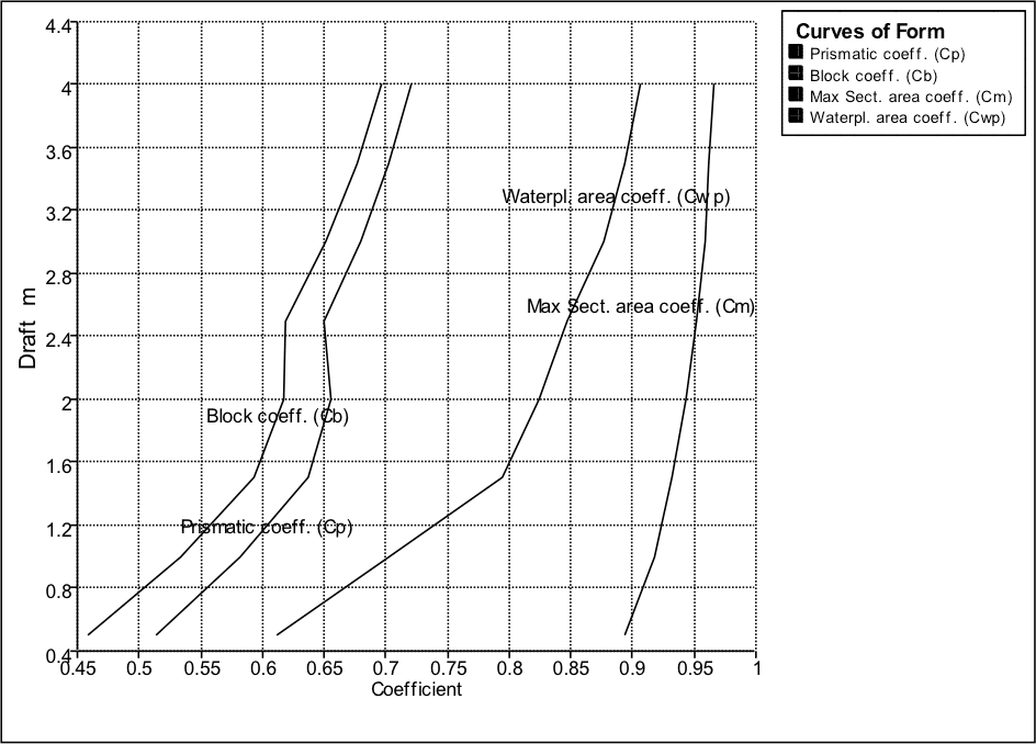
Though these parameters are not important for the crew, they play important role in optimizing the hull shape, and fairing the hull to a fine shape. If you notice the nature of the curves in the figure, the curves are not smooth. This implies that the hull at this stage of design, is not completely smooth, and would result in increased resistance. The same also applies to all the hydrostatic curves. Both these curves, along with the sectional area curve of a ship are simultaneously referred to, at each stage of hull modification, until a smooth set of curves are obtained.
This article has acquainted you with the hydrostatics of a surface ships, the understanding of which will play a vital role in studying the stability of ships. You can now recognize each hydrostatic parameter that appears further, its significance, and how it is represented on the stability book of a ship in form of curves.
The next article will discuss the basic concepts of ship stability which includes an introduction to intact stability and damaged stability, with detailed understanding of evaluation of intact stability of a ship along with various cases that affect the same.
Disclaimer: The authors’ views expressed in this article do not necessarily reflect the views of The Marine Learners. Data and charts, if used, in the article have been sourced from available information and have not been authenticated by any statutory authority. The author and The Marine Learners do not claim it to be accurate nor accept any responsibility for the same. The views constitute only the opinions and do not constitute any guidelines or recommendation on any course of action to be followed by the reader.
The article or images cannot be reproduced, copied, shared or used in any form without the permission of the author and The Marine Learners.