Offshore lifting is a common operation in offshore construction or installation projects at sea. In this article, we will discuss offshore lifting operations and associated engineering analysis, safety precautionary measures, contingency plans, and challenges involved in lifting.
We will address these challenges and will explain in detail, how to tackle these problems.
For example, a process module to be installed on FPSO. Let’s assume the weight of the module is about 1000 Tonnes.
Let’s consider the weight of the module is about 1000 Tonnes. The most basic requirement is the lifting crane supposed to be of a capacity higher than 1000 tonnes (As per norms, crane safe working load to be at least 1.25 times the weight of the equipment). Let us discuss how the load of the module is transferred to the crane. Load of the equipment is transferred to the crane through the lifting pad eyes, spreader beams, lifting wires, shackles etc. (In general, these are called as lifting gears). Hence all the lifting gears involved in the load transfer must be able to withstand the load imposed during the lifting operation. To analyse whether a lifting gear can withstand a given load, we must first estimate the load imposed on the lifting gear.
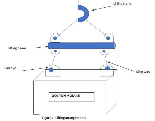
In the above lifting arrangements, the 1000 tonne module is lifted using 4-pad eyes. Hence each pad eye is subjected to a load of 250 tonnes. The sling wires transfer the load to the lifting beam. There are four wires used, hence each wire is subjected to 250 tonnes (For time being we will ignore effects due to sling angle). The sling wire transfers the load to the lifting beam. In this case, the lifting beam is subjected to 1000 tonnes (Note: the two pad eyes that transfer the load is subjected to 500 tonnes each).
SLING GEOMETRY
In the above load assessment, we assumed the sling angle to be 90 degrees. In reality, it is not 90 degree. The point of suspension of the equipment should always be in line with the centre of gravity of the equipment to avoid tilting of the equipment.
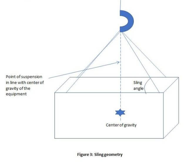
Loading changes drastically with the sling angle. Following tables depicts the comparison of loading at 90®, 60®, 30® .
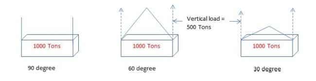
| 90 degree | 60 degree | 30 degree |
| Each sling is subject to a load of 500 tonnes
0% increase
|
Applying resolution of forces concept,
Load on one sling = Vertical load/sin(60). Vertical load =500 tonnes. Therefore load on one sling = 500/sin(60) =500/0.866 = 577.35 Tons
15.47% increase |
Applying resolution of forces concept,
Load on one sling = Vertical load/sin(60). Vertical load =500 tonnes. Therefore load on one sling = 500/sin(30) =500/0.5 = 1000 Tons
100% increase = 577 |
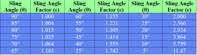
From the above table, we can understand how loads can drastically increase with the reduction in sling angles. Sling angle factors are critical in load assessment. Following Sling angle factors are given in ANSI B30.9.
-In figure 3, the lifting arrangement was depicted without the use of lifting beam. Usage of lifting beam helps to reduce the sling angle and thereby load on the sling.
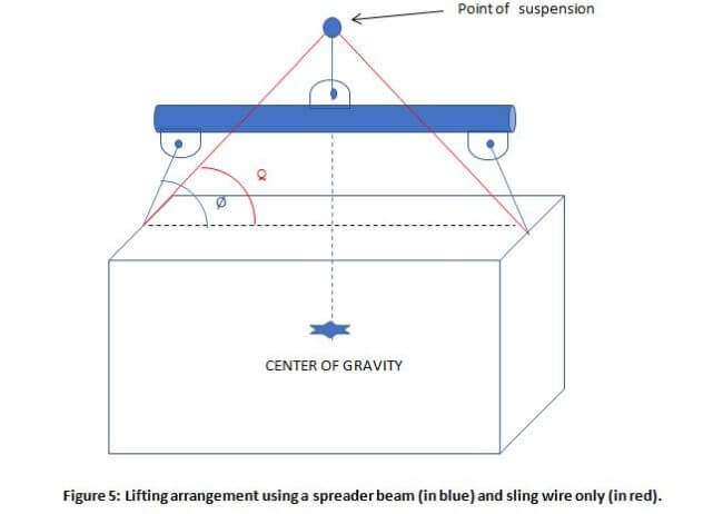
From the above figure, it is evident how sling angle is increased using spreader beam (Ø>Q).
[the_ad id=’172861′]
Bending and Buckling strength of the beam has to be assessed and proven they are within the requirement.
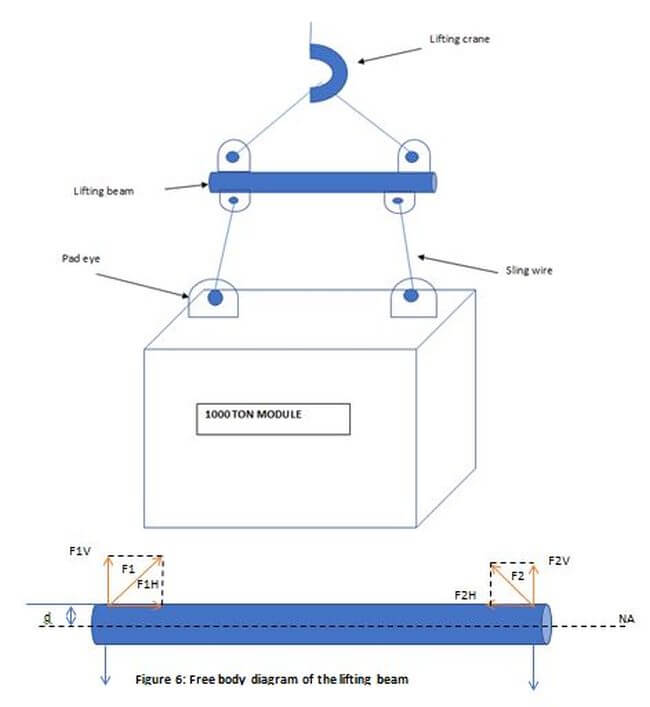
Using Euler beam equation, we can find Bending stress s = M * I/y
Where s is Bending stress, M is the Maximum bending moment, while “I” is the second moment of area and y is the distance from the neutral axis.
In this case, the maximum bending moment can be evaluated as F1H* d.
The second moment of area is πr4/4 (Since the cross section of the spreader beam is circular.
As per class, s evaluated should not be greater than 0.6 * yield strength of the spreader beam material.
Note that in the above evaluation, the weight of the beam is ignored.
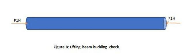
F1H and F2H are potential forces to buckle the beam. Buckling check can be done by evaluating the Euler critical load. If the subjected load is greater than the Euler critical load then the beam will buckle.
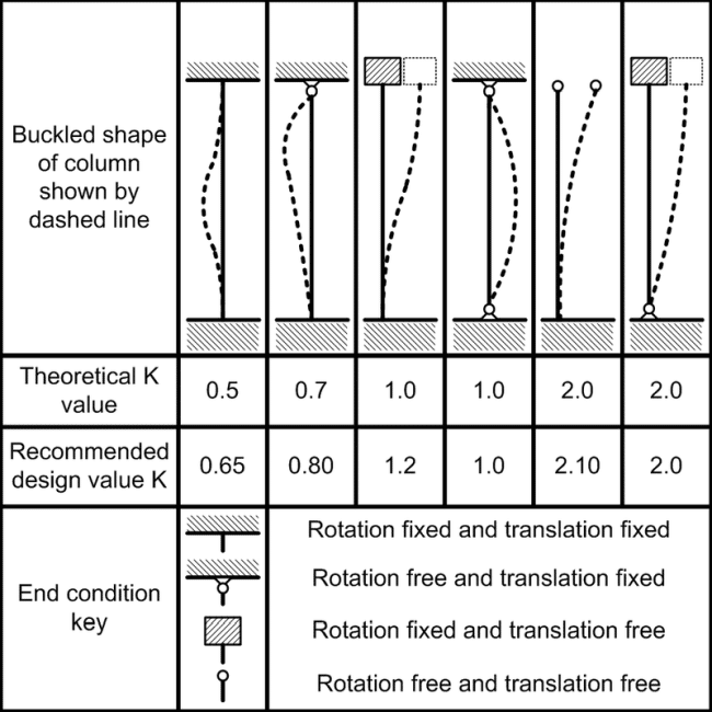
Euler critical load P is given by : π2EI/(KL)2
Where E is the young’s modulus of the beam material, I is the Moment of Inertia , K is effective length factor and L is the unsupported length.
Below figure can be used to find out the effective length factor (K).
In addition to the buckling check, compressive stress due to the forces F1H, F2H must be less than 0.6* yield strength of the material.
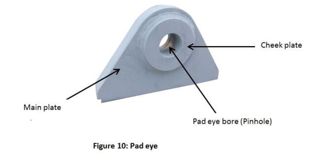
Pad eye is subject ted following forces:
1) Shear force
2) Axial force
3) Normal force
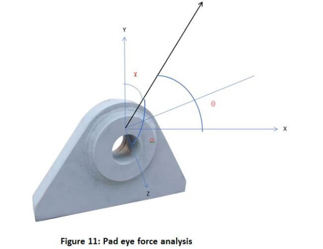
The tension T should be resolved in 3d to estimate the shear force ( the force that is parallel to the plane), axial force ( the force that is in-line with the axis of pad eye ), normal force ( the force that is normal to the plane).
[the_ad id=’173168′]
Shear stress = shear force/shear area.
Shear stresses are to be less than 0.4 times the yield stress.
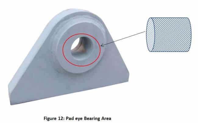
Bearing stress is the contact pressure onto a body. It is given by Design load/bearing area.
Bearing stresses are to be less than 0.9 times the yield stress.
As seen earlier, Using Euler being equation we can find Bending stress s = M * I/y
Where s is Bending stress, M is the Maximum bending moment, while “I” is the second moment of area and y is the distance fro the neutral axis.
Bending stresses are to be less than 0.6 times the yield stress.
NOTE: Pad eye bore has to be compatible to the lifting shackle. For example, 20 Tonnes pad eye bore diameter should be large enough for a 20 Tonne shackle pin.
As we have seen earlier the loading on the pad eyes are multiaxial, hence there is a combination of shear and bending. Vonmisses stress gives an equivalent stress that can be used to assess the strength in multiaxial loading condition.

Offshore lifting is dynamic in nature due to the ocean waves, currents, wind forces etc. It is important to include the dynamic effects into the calculation as these can significantly influence the results.
Relative motion between the crane tip (carrying the object to be lifted) and the waves should be established. The time period of crane tip motion can be formulated as follows:
T = 2π x √((M +A33 + θ)/k)
where
m = mass of hoisting line per unit length [kg/m]
L = length of hoisting line [m]
M = mass of object in air [kg]
A33 = heave added mass of object [kg]
K = stiffness of hoisting system
θ = adjustment factor taking into account the effect of the mass of hoisting line and possible soft springs.
The Crane tip motion period is compared with the significant wave period and ensured both are not close to causing resonance.
All the formulae we saw earlier in this article did not account for dynamic effects. They are good to use in a static condition (still water condition). Lifting in dynamic conditions requires slight modification to the formula. All the equation has to be multiplied by a factor called dynamic amplification factor.
Total force = Force (Static) X DAF.
Various classification societies have given recommended DAF for various scenarios which can be used in the calculations. DAF can also be established from model testing.
Bumper and guides are positioned in such a way to prevent the lifting object (for example module) to strike against any other structure or object during the lifting operation.
Load on the crane ( and lifting gears) lifting a submerged object can be evaluated by the following equation:
F(static) = Mg – ρVg.
Where M is the mass of the object.
g is acceleration due to gravity, 9.81m2/s.
ρ is the density of water.
V is the displaced volume of the submerged object.
The article gives a brief summary of offshore lifting. In addition to the topics covered (Sling geometry, Sling wire analysis, Lifting beam analysis, Pad eye analysis and Dynamic effects during lifting) in the article, mooring analysis, motion analysis does play a critical role in offshore lifting analysis. These topics are profound, hence will be dealt separately in a different article.
You may also like to read:
What is Basic Offshore Safety Induction and Emergency Training (BOSIET)?
How Subsea Components Of ROV Sustain Tremendous Seawater Pressure?
Disclaimer: The authors’ views expressed in this article do not necessarily reflect the views of The Marine Learners. Data and charts, if used, in the article have been sourced from available information and have not been authenticated by any statutory authority. The author and The Marine Learners do not claim it to be accurate nor accept any responsibility for the same. The views constitute only the opinions and do not constitute any guidelines or recommendation on any course of action to be followed by the reader.
The article or images cannot be reproduced, copied, shared or used in any form without the permission of the author and The Marine Learners.